 Functional safety expert John Lindland (who has served on the Fiat Chrysler Automobile Corporate Functional Safety Steering Committee) presents the first in a series of articles that set out to describe the intent of functional safety, and how to design for functional safety, drawing on content from a soon-to-be published book, ‘Design for Functional Safety, The Concept Design Phase‘.
“ISO 26262 Road Vehicle’s 12-part series has a large number of requirements,” explains Lindland. “Satisfying each individual requirement can seem to be confusing. Design for Functional Safety is a seamless analysis that spans concept, system, hardware, and software. It shows how to reduce the total amount of work and produce exceptional results. Some 80-95% of causes are foreseeable and avoidable. Design for functional safety helps to identify and prevent these causes from being included in the design. The end result is exceptional quality, reliability, and safety.”
An Overview of Road Vehicles Functional Safety ISO 26262
The following article lightly covers all 12 of the parts of ISO 26262 Road Vehicle Functional Safety. It provides a solid overview of the ISO 26262 work product parts. These are Part 3 The concept design phase, Part 4 the system design phase, Part 5 the hardware design phase, and Part 6 the software design phase. The article interweaves design for functional safety and introduces the concept of statistical capability of the design as well as the five levels of mastery of function.
The United States Department of Transportation and the National Highway Transportation and Safety Administration have published a series of autonomous vehicle policies that govern these vehicles when used on public roads. They identified that ISO 26262 Road Vehicle Functional Safety is the appropriate standard to manage the development and production of partially automated and highly automated vehicles.
The premise of achieving product certification to ISO 26262 is based on controlled business processes that cover customer negations/product offerings, product design, product verification/validation, purchasing, receiving inspection, production, production validation, inspection and testing, product support, service and decommissioning. ISO 26262 Part 2 requires that a company be registered with the International Automotive Task Force (IATF) 16949 Automotive Quality Management System. ISO 26262 Part 8 defines supporting business processes that directly relate to ISO 26262. These supporting processes are included in any IATF 16949 business structure. As a result, the IATF 16949 registration audit includes the scope of ISO 26262. The requirements can be added to their appropriate related automotive procedures, instructions and records. They can also be standalone procedures, instructions and records. Automotive manufacturing companies require that their Tier 1 suppliers be registered with IATF 16949. Autonomous design and manufacturing companies are required to be registered with IATF 16949 and follow the DOT autonomous vehicle policies and the federal motor vehicle safety standards. As an example, retrofitting an OEM truck/vehicle invalidates the OEM’s FMVSS testing for steering systems, braking systems, acceleration/deceleration and potentially other systems, even while driving in manual mode.
Autonomy is magnitudes more complex than normal machine-level negative feedback electronic control systems. This is the premise of ISO 26262 and adds to the normal and customary design, safety and business practices of IATF 16949. Some countries have more than one nationally recognized automotive quality management system (e.g. VDA). Each country can require its automotive quality management system to be used instead of IATF 16949. Each country might have its own motor vehicle safety standard tests. IATF 16949 requires that calibration and testing comply with the ISO 17025 Calibration and Lab Facility standard. This can be included within the scope of the IATF 16949 registration.
Safety cases are valid only when they are produced in this controlled environment. This ensures that safety in the future will be equal to or safer than the original safety case. The safety case must always be consistent with each design’s technical data package. Safety cases are updated every time a design is changed. FMVSS requires that tests be performed under these controls. FMVSS test records are not approved by the DOT. They are to be available upon request by the DOT/NHTSA. The same will be true for all functional safety case evidence.

Autonomous design and manufacturing companies that test on public roads or offer the sale of autonomous vehicles for use on public roads are required to complete their appropriate FMVSS tests. Automotive OEM companies must satisfy all FMVSS tests for their vehicles prior to production sales. When an autonomous manufacturing/design company retrofits an OEM vehicle with an autonomy system, it has broken the FMVSS/OEM test integrity. The OEM FMVSS test that validates the steering, braking and acceleration/deceleration system is no longer valid. When an autonomy company is in doubt about test applicability, it is required to ask the NHTSA for a ruling and test guidance. Rulings are part of the design’s safety case. Autonomous design companies that do not follow ISO 26262, IATF 16949 and ISO 17025 will be more exposed to legal liability than companies that follow the recommended processes. Regardless of the fault that causes an injury/fatality, ISO 26262 would have provided the process that is structured to discover and avoid the hazards that created the crash. Non-compliance with federally recommended best practices is the wrong way to begin a lawsuit defense.

Design for Functional Safety – the Concept Design Phase covers the five levels of autonomy (SAE J2016: 2018, Table 3.1). The L1 and L2 design levels are driver-assist functions. An L1 design will control either longitudinal controls (acceleration, deceleration/braking) or lateral controls (steering). An L2 design will control both longitudinal and lateral functions. In both cases, the driver is fully responsible for object and event detection and response for all dynamic driving tasks. The L1/L2 driver assist designs help overcome moments of driver inattentiveness (Figure 3.6). These solutions are normally simple and direct machine control systems. However, they can be designed with excellent capability and provide significant risk reduction. L3 solutions are highly automated with a limited operating domain definition where the driver must take over the dynamic driving task when the system has reached the limits of the technical solution. The loss of control line relates to both normal and complex driving scenarios. A capable highly automated L4/L5 design will have the capability to safely maneuver all complex driving scenarios even while experiencing function faults/failure modes.
The basis of 7FM Design for Functional Safety
One hundred percent of the ISO 26262 requirements can be directly addressed and provide extremely good guidance and benefits to any design team. The Design for Functional Safety series will provide clear step-by-step guidance to design safe autonomous systems and to directly satisfy all requirements. Satisfying all requirements is a natural byproduct of creating a design of high quality, capability, reliability and safety.
All designs at all levels are made up of sequences of functions. Functions fall into each other like dominos. When a function falls poorly it is in a fault state and will affect the next function. This turns the function sequence into a failure mode/fault sequence. This generates a fault state map of the fault relationship. Some sequences have cross relationships where a function’s output is used by two or more following functional paths. All autonomy functions begin with sensor functions and their sequence of functions ages and matures into the ending vehicle-level functions (steering, acceleration/deceleration, braking). These are the functions that are directly responsible for creating a precrash scenario. All designs and their complexities can be modeled, analyzed and improved, and be directly definable and tractable.
7FM Design for Functional Safety avoids the need for extra project managers to follow up on the problems that were not avoided. Eighty to Ninety-five percent of all causes are identifiable and avoidable by following 7FM Design for Functional Safety. When this is compared with the Pareto Principle that 20% of causes produce 80% of the effects, avowing just 8% of causes means that well over 99% of effects are avoidable. This is true even when functions enter a fault state. Causes that are not avoided will tend to have extremely long mean time between failures. Some causes will be random causes that no amount of study will avoid. In both cases, function fault detection will find each function fault/failure mode and activate the appropriate safety mechanisms designed for each specific function and its faults. A precrash scenario and its hazards are avoided.

Functions need to have clearly identified requirements that they must objectively satisfy (Figure 4.7). These functions must continue to meet these requirements over the active life of the autonomy solution. This means that the design parameters (input requirements) must resist change from all degradation factors such as temperature, vibration, chemicals, debris and radiated energy. Each output requirement can fail to be met. When a requirement is not met, the function is in a failure mode or fault state. This means that a function’s failure mode can be multidimensional. The first-level effect of a failure mode is the specific way that each requirement is not met. What follows is a temporal fault sequence of effects that can eventually reach a vehicle-level function. This is definable and traceable. Design verification, as described in the original quality management system MILQ9858 (which became ISO 9001), states that successful validation always follows successful verification. Verification is tests of theory and includes all simulations. Simulation cannot be used to count miles or to validate vehicle-level functions. Verification suggests that moving the design to validation will not be an unwise waste of money. Verification addresses each output requirement in turn and asks a simple question, “Which of the inputs are required to satisfy the output requirement? Which parameters are required to survive degradation? Which parameters are random environment factors that need to be monitored to predict function failure?” And so on. After the design input requirements are fine-tuned and suggest that the function can meet all requirements, the design can move forward and be finalized.
All functions can fault in one of seven ways that are useful for exploring design requirements and design parameter optimization. The seven function faults are the seven failure modes that are explained in some detail in the HARA/Safety Goals and Functional Safety Concept/Functional Safety Requirements. These are function failure modes of Omission [O], Excessive [+], Incomplete [-], Erratic [V], Uneven/biased [U], Too Slowly [+T], and Too Quickly [-T]. During the creation of the 7FM functional block diagram, these shorthand notations are added to each function. Each fault state can be directly related to all the subsequent failure modes created (the sympathetic failure responses). Functions and fault states are clearly described. Fault detection becomes a normal part of creating a solid design. Safety mechanisms become a natural result of fault detection. Each failure mode might have a range of failure strengths that range from an anomaly to a complete omission. These different strengths have different impacts/hazards and each can have its own specific safety mechanism. These will cause a fault sequence that can have different levels of vehicle-level function faults (the same seven failure mode fault states). This means that all fault sequences are traceable through the system and can predict the vehicle-level fault state(s) created. These are traceable to specific precrash scenarios and their specific hazards (vehicle, pedestrian or pedal cyclist). These are traceable to each vehicle-level function’s safety goals. Fault arbitration becomes a simple mathematical solution. The first fault in a series of faults owns the safety mechanism. This avoids any ‘spider-web’ analysis. One hundred percent of each function’s input requirements and output requirements are definable. Each output requirement defines its related validation tests.
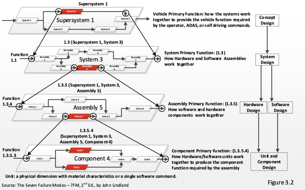
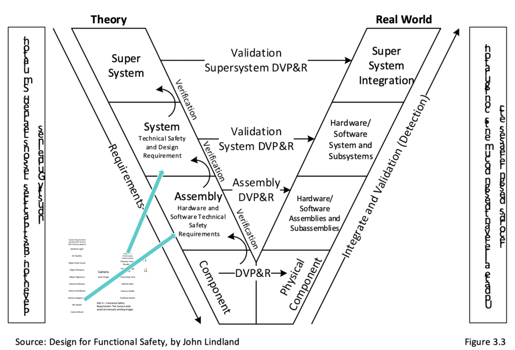
All designs have hierarchies. Figure 3.2 shows a function-based configuration. Each functional block of a lower level explains how each higher-level function is created. This provides a seamless top-down design of functions. A design is created top-down and it is validated bottom-up (Figure 3.3). Each function has its input requirements (level of study) and output requirements (one level higher). Verification asks the question, “If all the input requirements are met, will all output requirements be met?” The top level is the super-system and this is the autonomous vehicle operating in its driving environment (ODD). This is the integration of the autonomous system’s functions interacting with the vehicle’s system-level functions. It asks the question, “How do the autonomy system’s output functions work with the vehicle’s system functions to produce safe autonomous vehicle-level functions?” Systems ask, “How do autonomy assembly output functions work together to produce autonomy system output functions?” Assemblies ask, “How do component output functions work together to produce assembly output functions?” Components ask, “How do units work together to produce component output functions?” At this last level, there are software units and physical dimensions that have defined material properties. Energy enters the material and is focused by dimensions and transferred through a component to exit at a different dimension with material properties. 7FM Axiom 1: Dimensions make a function work and materials make the function last. Design for Functional Safety begins with the Concept Design Phase (Figure 3.2). It will be followed by the System Design Phase, the Hardware Design Phase and finally the Software Design Phase. The goal of each phase is to clearly describe each design analysis, design optimization, verification and validation, fault detection and safety mechanisms. The result is an autonomous design that has been produced by a defined design process that is tractable and manageable. The result will produce statistically capable and validated vehicle-level functions that have extremely low failure (hazard) rates.
Each function’s fault states are added to its specific function configuration. Omission is x.1, Excessive is x.2, Incomplete is x.3, Erratic is x.4, Uneven/Biased is x.5, Too Slowly is x.6 and too quickly is x.7. This means that all fault states can be stored when any specific function fault is detected. The topic of configuration is clearly explained in Design for Functional Safety – the Concept Design Phase.
All ISO 26262 requirements are beneficial and directly satisfied by a solid design process. Eighty to ninety-five percent of all causes are foreseeable and avoidable. Design parameters can avoid or delay failure modes through the active life of an autonomy system’s active phase. All system-level faults can be detected as they occur and activate a safety mechanism and safely avoid a hazard even in complex driving scenarios while experiencing system-level faults. All system-level faults can be traceable to more granular unit-level causes.
