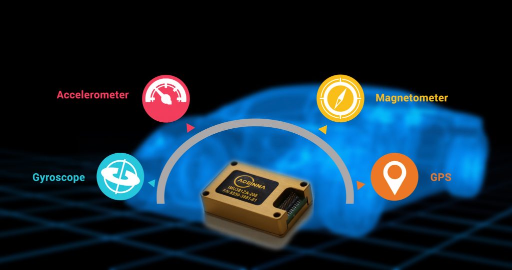
All about IMUs: James Fennelly, product manager, inertial measurement systems, ACEINNA, considers how advancements in inertial measurement unit (IMU) technology could improve positioning accuracy and operational safety for autonomous vehicles.
The future of autonomous vehicles is based upon several strategic sensing technology advances that will enable high rates of safety and precise positioning capabilities.
The most significant advancement required for the success of autonomous vehicles is the real-time, constant and accurate position and motion of the vehicle throughout any environmental changes. Autonomous vehicles of all types – cars, trucks, buses, drones, robotic systems, etc – all must be able to determine where they are and where they are going in all weather, temperature and landscape environments, as well as in situations where GNSS signal is lost or compromised.
One of the most critical sensors in all positioning systems is the inertial measurement unit (IMU) which measures the fundamental physics of motion, acceleration and rotational velocity. Fundamental understanding of how a vehicle is moving in time and space is critical for autonomous applications and IMUs are the most dependable sensors as they cannot be jammed or spoofed and are not affected by weather and other environmental conditions.

IMUs do not suffer from multi-path effects or signal degradation in urban canyons or forested roads.
In an autonomous system, IMU data is fused with GNSS, vision and other detection and ranging systems to fill in gaps between GNSS updates and to safely navigate for short periods when GNSS and/or other sensors are compromised. The IMU data is always available and is an integral part of any autonomous vehicle system and is relied on to maintain safe vehicle operation in challenging environments.
High-performance IMUs capable of dead reckoning accurately for long periods of time do exist today. They can be found in military systems used in missiles, in fighter aircraft, in helicopters, in spacecraft and satellites, and large commercial aircraft. These high-performance IMUs use technology like ring laser gyroscopes (RLG) or fiber-optic gyroscopes (FOG). The technology is proven and dependable, but it is cost prohibitive for higher volume commercial applications.
IMUs with the performance required for autonomous vehicles are still not available at the cost needed for higher volume commercial applications. A significant step function improvement in sensor performance, specifically when the vehicle is operating under a dead reckoning situation, for seconds, or potentially minutes at a time, is needed. Micro-electrical mechanical system (MEMS) IMU sensor advancements and advancements in sensor fusion algorithms are closing the performance gap and have promise to achieve the affordability required for wide-scale deployment.
There are two critical parameters designers are working with to improve in MEMS gyroscopes, angle random walk (ARW) and bias instability (BI). These parameters provide autonomous system designers a common benchmark that is used to compare relative performance of gyroscopes and determine the time envelope of safe operation.
Angle random walk is a measure of short-term noise in the rate sensor. It is commonly expressed in degrees per root-hour and is calculated from the one second point on the Allan deviation plot of a gyro output. It is important because the rate signal is integrated to determine attitude of the vehicle (roll, pitch, yaw) and integration of noise results in random error.
A common and often used thought experiment to illustrate this random error effect is to imagine yourself standing at the center of a soccer pitch with a coin in your hand. You flip the coin 100 times. For every ‘heads’ you take a 1m step to the left and for every ‘tails’ you take a 1m step to the right. Most likely you end up near where you started, however if you repeat this 1,000 times, you will find yourself at various distances from the center point and occasionally at either end of the pitch. If you look at the statistics of the experiment results, you will see Gaussian probability distribution with the mean located at the center of the pitch. The step size determines the standard deviation of the distribution. Smaller step size reduces how far you can theoretically get way from the center of the pitch. A 1cm step size results in a much tighter distribution than a 1m step. The ARW specification of a gyroscope is analogous to the step size in the thought experiment above. Smaller is better.
Bias instability (BI) is also derived from the Allan deviation plot of a gyro output. Commonly expressed in degrees per hour, it is calculated from the point where the slope changes from negative to positive and represents the long term drift of the gyro bias. Bias drift can be thought of as a change in DC offset applied to the output of the gyroscope. During the integration of the rate signal, any error in the bias will quickly accumulate as angle error. Another thought experiment is used to illustrate its affect.
Imagine a vehicle is traveling through a perfectly straight tunnel. Let us say the vehicle takes one half hour from one end to reach the other end of this perfectly straight tunnel traveling at 20km/h. If the yaw gyro being used to navigate and keep the vehicle on course has a bias instability of 3 degrees per hour, by the end of the tunnel the vehicle heading will be greater than 1.5° off course. Traveling at 20km/h, the vehicle will be going to the left or right 15cm every second, likely resulting in the vehicle hitting another vehicle or wall well before the end of the tunnel is reached.
Advanced sensor fusion using Kalman filtering can largely correct for both of these errors during normal vehicle operation. The pitch and roll gyroscope errors can be removed within an IMU using the Kalman filter and calculations of pitch and roll made using accelerometer signals measuring acceleration due to Earth’s gravity. The algorithm tracks and corrects for the bias drift and corrects for the ARW error.
The yaw axis is arguably the most important in land vehicle applications, and because the yaw axis is orthogonal to the gravity vector, acceleration signals from Earth’s gravity cannot be used as a reference for correction. Instead, other aiding signals derived from GNSS and other sensors on the vehicle are used.
Up until the point where the aiding signals are lost or compromised, the sensor fusion algorithms have been keeping track and correcting for the yaw gyro errors. Once the aiding signals are lost or compromised the autonomous system must rely on the raw performance of the yaw gyro signal. ARW and BI are two of the critical parameters that will determine how much position, velocity and heading error will build with time.
Within the industry, the yaw gyro performance remains a constant issue and is driving manufacturers to improve the sensitivity and overall performance of gyros for autonomous systems striving toward bias instability of much less than 1°/hr.
Thus, as we progress toward fully autonomous driving, higher levels of autonomous applications and freedoms will be enabled by the performance of more accurate and highly stable IMUs, specifically on the Z axis or yaw gyro performance.
About the author: James Fennelly, ACEINNA Inc, received his BS EET from the University of Massachusetts. He has been working for the past 15 years with MEMS inertial sensors, including component level acceleration sensors and system level products. He is responsible for defining new products at ACEINNA Inc to meet the needs of emerging applications in the inertial sensing market.


