 – Defining crash avoidance requirements and safety goals (Part 3 of 3)")
The following feature is a shortened, edited version of a rough draft extraction from 7FM Design for Functional Safety, the Concept Design Phase, by John Lindland, presented in association with ADAS & Autonomous Vehicle International, and available to download in its original, full length, here.
This section will show how to define and link each of the vehicle level function’s (VLF’s) failure modes/fault states to each National Highway Transportation and Safety Administration (NHTSA) pre-crash scenario. The NHTSA patterns are all ‘after-the-fact’ groupings of scenarios as to what immediately precedes a crash. These patterns are across all possible road configurations, and weather and vehicle conditions. After the fact means that if one watched the crashes occur, one could describe the spatial and time sequence relationships as definable by the human mind. The goal is to slice an ODD into tractable and solvable road segments that are homogeneous to each other where these patterns become recognizable. While documenting the patterns that must be recognized and to which the AV must respond, the HARA will uncover unsafe item definition assumptions and functional limitations. New design elements, functions and functional interrelations are added to remove risks. Functional safety requirements are assigned to elements and functions to reduce or eliminate the probability that a VLF will enter a failure mode/fault state (enter or create a pre-crash scenario). Safety goals define when VLFs can be considered free from unreasonable risk.
There are 36 NHTSA pre-crash scenario structures that cover the millions of crashes that occur every year. All crashes fall into these 36 patterns, which must be defined by macro/micro spatial and time sequence patterns that the system can recognize and to which it can safely respond. Pre-crash scenarios include AV/vehicle failure causes, single AV crashes, AV crashing into HazObs, and HazObs crashing into the AV. How to minimize vehicle failure causes will be solved at the system design phase. The ODD is collapsed into representative road segments. Each road segment must be homogeneous in structure, flow entrances, exits and pass-through flow. How single and multivehicle crashes occur must be clearly defined and structured into spatial and time sequence patterns. These become the AI/ML lesson plans that build their worldview.
Three tables will be used to understand and document hazardous situations. Tables 3.4, 3.5 and 3.6 exceed the systematic analysis requirements of ISO 26262 Part 3-6.4 Documenting the Hazard Analysis and Risk Assessment: HARA. One set of tables is used for each representative road segment, specific point on the map and general/regional road constraints such as accidents, construction and farm equipment. The teams will find that risks have common structures that overlap and core solutions that will solve these common risks. The Pareto principle is useful at this point. Eighty percent of risks are solved by 20% of solution efforts. These are the right of way/DDT solutions. This is the AV’s core design. Fifteen percent of the risks are emergent and road/path blockage risks. These will be 30% of the solution efforts. Failure to solve any of these will cause extreme negative public reactions. Public comments will be that the AV could not handle obvious and easily understandable situations and caused a crash, injury or fatality. Five percent of the risks are sudden emergent risks and this will cover roughly 50% of the total solution efforts.
Linking risks to vehicle level functions
There are seven useful potential function-based failure modes. The foundation of each will be discussed in the following chapter on the functional safety concept. All technical safety requirements can be fully defined from these seven failure modes/fault states. Potential failure modes relate to when the planned path creates a pre-crash scenario that means that the AV’s planned and executed functions were inappropriate, or the AV approaches a developing or fully formed pre-crash scenario and it must respond to reduce risks.
The seven failure modes are [O] Omission of function or required change, [+] Excessive function, [-] Incomplete function, [V] Erratic/Unstable function, [U] Uneven/Biased function, [+T] Too slow/late function, and [-T] too fast/soon function. It is rare that all seven failure modes apply for a given function for a single road segment. The cell contains the pre-crash scenario or a specific crash into another vehicle, pedestrian or pedal cyclist. This means that if the AV is performing a maneuver, even if it is going straight, the failure mode would create or enter a pre-crash scenario.
Table 3.4 can be used for all autonomy SAE L1 – L5 autonomous designs. It can also be used for vehicle level functions controlled by automotive electronics and software closed loop systems L0 – L2. The pre-crash scenario column contains the hazards that will be copied into each of the VLF’s failure mode’s cells. For example, failure to accelerate (omission of acceleration) will mean that the AV does not clear an area and might get struck. Any rear or side crash into the AV can be caused by this omission.
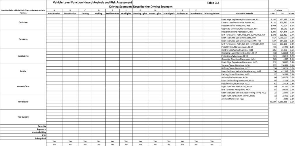
The pre-crash scenarios in Table 3.4 come from Table 3.20. The goal is to relate each potential VLF failure mode to all possible pre-crash scenarios it might potentially enter or create. If a specific HazOb will not be present in the road segment, it is removed from the analysis. This analysis will show that multiple VLF’s share responsibilities for portions of some of the pre-crash scenario. This means that perfecting one VLF might not fully remove risk. Following a planned path requires steering, throttle and braking.
Table 3.5 documents the representative road segment’s driving environment. This defines what the sensors can observe, the events that will be created, what must be detected and the constraints for the AV’s responses.
Table 3.6 will assign functional safety requirements to each of the concept phase design elements.
The following are answers to the ISO 26262 Part 3 Item Definition for a Forward Crash Avoidance system. Reference the standard, look at the clause requirement, then read how it is answered in this section.
ISO 26262-Part 3, 5.4.1 a) Identify the legal requirements that the design must satisfy. The forward crash avoidance system is not covered by FMVSS and does not need to be approved by each state in which it is driven. The system will be a general release and its general FMVSS requirements will be satisfied by general FMVSS testing.
Essential comments for 5.4.1 a) autonomous systems that assess the driving environment and control VLFs with special consideration for FSD/AKA SAE L2+ and SAE L3-L5 systems. The system must satisfy the Federal Motor Vehicle Safety Standards (FMVSS) before being tested or driven on public roads. NHTSA has two autonomous vehicle policies that it relegates to the states for enforcement. These are mandated when a state’s autonomous vehicle test permits require compliance with FMVSS/NHTSA. NHTSA policies state that ISO 26262 over the road functional safety is the most appropriate safety standard. As of this writing, the policies are not enforced. Enforcement will likely occur after the first extremely visible crash with national coverage or a class action lawsuit. ISO 26262 was developed by international automotive OEM manufacturers and their Tier 1 OEM system manufacturers to be the vehicle safety standard. ISO 26262 Part 2 states that the IATF 16949 automotive quality management system is required. It represents current best practices. Automotive OEMs require all Tier 1 suppliers to be registered to IATF 16949. The scope of the IATF 16949 registration must include the ISO 26262 core processes as required to satisfy ISO 26262 product safety certification. Registration to IATF 16949 provides objective evidence of compliance with ISO 26262 practices. Product safety certification to ISO 26262 is objective evidence that a safety case supports the attainment of safety goals.
ISO 26262-Part 3, 5.4.1 b): The design is an SAE Level 1, single-function, forward-trajectory braking crash avoidance solution. It measures the speed and the time distance to a forward obstacle. It warns the driver of a forward obstacle that might be a HazOb or might have substance but not involve a human. If the driver does not perform an avoidance maneuver, the system will apply brakes to stop the vehicle before the obstacle is hit. Obstacles include static large debris/objects (documented parameters), and HazObs: vehicles, pedestrians, and pedal cyclists. The system is active when the vehicle is turned on, in a forward gear, a driver is in the seat, while driving on all roads, and in all parking lots. The system is disengaged while the vehicle is in neutral (e.g. car wash, being towed).
ISO 26262-Part 3, 5.4.1 c): Forward detection of objects is vehicle speed and speed differential dependent. Forward detection is object trajectory dependent. Sensors must be able to detect objects that are on a near-time interception trajectory with the front of the vehicle. This is the point where the team must differentiate what is and is not part of the technical solution. Example: The system is concerned about front vehicle object impact. It is not concerned with the side impact of the vehicle by other vehicles, pedestrians or pedal cyclists. The sensors must have a wide enough angle to detect objects that will cross the forward path of the AV from any potential path. This includes vehicles that overtake and pass the AV only to cross the AV’s path and then brake aggressively. The AV must be able to track the trajectory of all forward HazObs that might develop an intercept path to the AV’s right of way. Critical late intrusions into the path of the AV are unavoidable. It will not include the option of accelerating or turning as an intercept/crash avoidance solution.
ISO 26262-Part 3, 5.4.1 d): The primary sensor is a forward-looking three-band imaging radar that has three distance zones and angles of detection. The imaging radar can distinguish speed differences of 1cm/second between objects. It does not include a high-definition map. The imaging radar detects relative angle of the HazOb to the sensor location/orientation to the true forward center of the AV. It has an error of ±1 lateral degree relative from the sensor forward center. It has a ±2 degrees vertical error to determine an object’s height and if an object is on the driving surface (e.g. on a bridge over the road).
ISO 26262-Part 3, 5.4.1 e): The primary shortfalls with the system are the velocity of the AV, latency of the system responses, the actual path of the AV, the AV’s lane, the road geometry (road width, lane center line/path, road grade, straightness/curvature, road condition, road surface type, etc), and object detectability of location, trajectory and intercept. If the road is curving and an object is off the driving surface, it can appear as if it is in the AV’s path and it is not. The opposite is also true. An object that is on the driving surface around a curve does not appear to be in the path of the AV and it is.
ISO 26262-Part 3, 5.4.1 f): The AV is responsible for the emergency brake commands to the actuator selected by the OEM vehicle manufacturer. The OEM vehicle manufacturer and the OEM brake manufacturer have provided the response curves for the braking system and stopping distances. The AV cannot improve the response curves. The AV controls can only degrade these performance curves. The degradation would be inappropriate and unsafe braking.
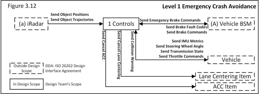
ISO 26262-Part 3, 5.4.2): The boundary of the item and its interfaces is shown in the functional block diagram (Figure 3.12). Its interactions with two other Level 1 items that are on the vehicle (adaptive cruise control and lane keeping) are addressed in the functional block diagram, function descriptions and safety requirements, and will be validated to ensure that there are no negative interrelations.
ISO 26262-Part 3, 5.4.2 a): The elements of the item are shown in the functional block diagram (Figure 3.12). The iRadar is a purchased element. The purchase will be covered by a development interface agreement. The 1 controls element hardware will be purchased and covered by a development interface agreement. The 1 controls algorithms will be developed in-house by the systems software design engineers. The wires, cables and connectors will be automotive safety critical grade and support current best practices for manufacturing, shipping, handling and installation.
ISO 26262-Part 3, 5.4 b): The emergency braking command will activate the vehicle’s braking system. If the braking torque overcomes road friction, the anti-lock brake system (ABS) of the vehicle will activate, which will allow the driver to maintain steering.
ISO 26262-Part 3, 5.4.2 c): The emergency brake command will cancel ACC, lane centering and engine torque requests to ensure that the driver does not have any resistance to their emergency maneuvering or steering. The cancellation requests will not affect driver commands of braking, throttle or steering.
ISO 26262-Part 3, 5.4.2 d): The emergency braking command is a subset of the advanced ACC items needed to control the speed going down a hill. Overspeed going down a hill is controlled by sending a braking command, which is the active method used for emergency forward crash avoidance. Emergency forward braking will use the same strategy, which will include the maximum braking coefficient and, if necessary, a priority interrupt command.
ISO 26262-Part 3, 5.4.2 e): The functional block diagram describes the allocation and distribution of the functions among interrelated systems and elements.
ISO 26262-Part 3, 5.4.2 f): The operational scenario that affects the functionality will be complex emergency maneuvering of the vehicle. In an accident scenario, the driver will be in full control of the AV. The emergency crash avoidance will detect critical intercepts, and if it activates the emergency brake commands it might interfere with a turning and acceleration command that the driver is making to avoid a crash. Any driver-commanded acceleration/braking activated after emergency braking must cancel emergency braking commands – send brake command-BSM, send throttle command-vehicle (functional safety requirement).
Example HARA: Table 3.4.1 is for the Level 1 forward crash avoidance system. The pre-crash scenario is the scope of coverage for the system while it is active. The commanded VLF is braking. Braking avoids HazObs that are, or will eventually be, in the forward trajectory of the AV. The system must correctly predict that brakes need to be applied to avoid an AV/HazOb intercept. This means that slowing a little, a lot or coming to a full stop will avoid a crash. Slowing a little means that the HazOb will safely pass in front of the AV. Coming to a full stop means that there is or will be an object/HazOb in front of the AV when it comes to a stop.
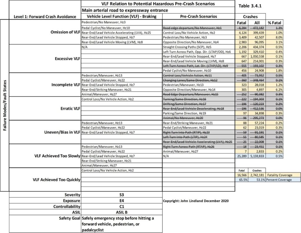
All pre-crash scenarios can be preselected in Table 3.4 before the HARA is performed. Then the team documents the object and event detections and response in relation to each pre-crash scenario. They will document all rational spatial/positional and time sequence patterns that exist for each representative road segment. The team documents hazards and how they will be avoided and the safety goal percentage reduction of crashes, injuries and fatalities. This creates a safety goal that can be objectively validated. The driver is responsible for all other hazards. Table 3.4.1 suggests that up to 65.5% of all fatalities can be avoided by a perfect forward collision solution. By the time the HARA is completed, the team should have a rough idea as to what portion might be addressed by the design. A solution with a 50% or greater national effectivity is a good first safety goal (save 8,283 of 16,566 lives).
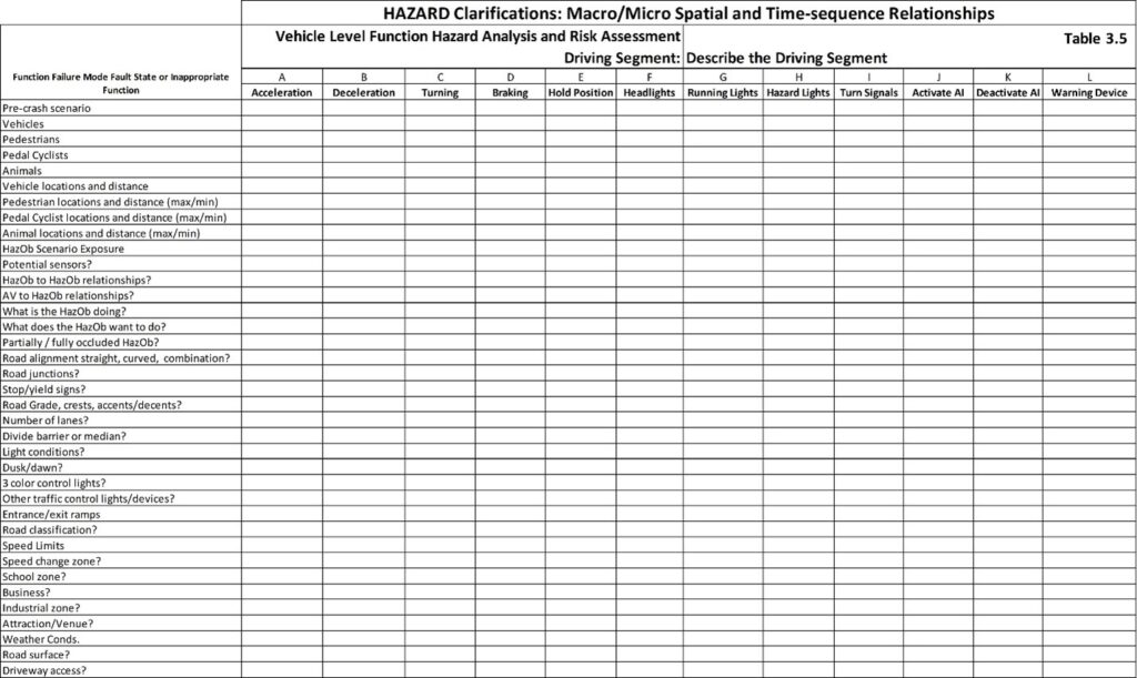
Table 3.5 is a general table that can be used. It relates all VLFs to potential HazObs. It has three sections of rows. The expected HazObs that are included in the representative road segment are documented. The HazOb exposure in the ODD is determined by the representative road segments. The quantity of each HazOb category in the driving segment at different times of day are the exposure to pre-crash scenario. The HazOb locations, relative position and trajectory compared with the AV as it drives is the specific exposure to front, side, turning, stopping and reverse pre-crash scenario.
Table 3.5.1 is an L1 example for a crash avoidance system. The first set of rows defines the HazObs and objects that sensors must recognize.
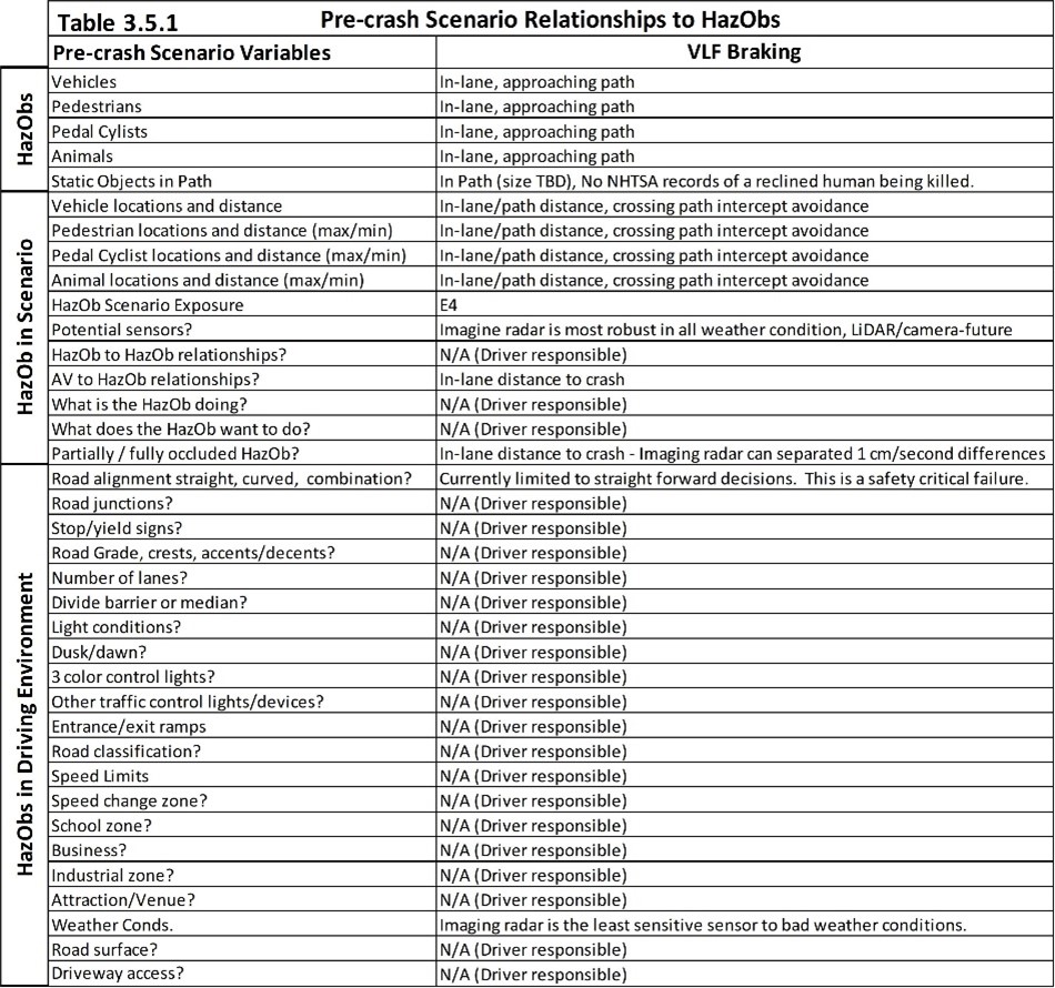
This second set of rows describes the HazOb in relationship to the scenarios or driving environment and the ASIL exposure risks for each function. Exposure changes based on the representative driving segment. For example, pedal cyclists on a controlled access road are extremely rare. Animals on a freeway are extremely rare in most areas of a country but are present in a few specific regions of a country. A human might be on the trouble strip of a freeway but it is extremely rare that they voluntarily step into the lane of an oncoming vehicle. With the exception of road workers and emergency responders, a pedestrian has no right of way on the driving surface of a controlled access road.
The third set of rows considers the driving environment, such as road geometries, interchanges, signage, control devices, time of day, speed limits, the types of residential/businesses being passed, and so on. These all relate to the fatality tables 3.21-3.28.
Table 3.6 is used to assign functional safety requirements for each concept/system level element function. Every element is a functional block on the 7FM functional block diagram. Every functional block has functions that leave the block and go to another element/block. The functional safety requirements are assigned as function’s input requirement or functional performance requirement (output). This will be included in the final functional safety concept. Once all functional safety requirements are assigned (system function level validation requirements), the safety goals will theoretically be met. Each pre-crash scenario and related safety goal receives one Table 3.6.
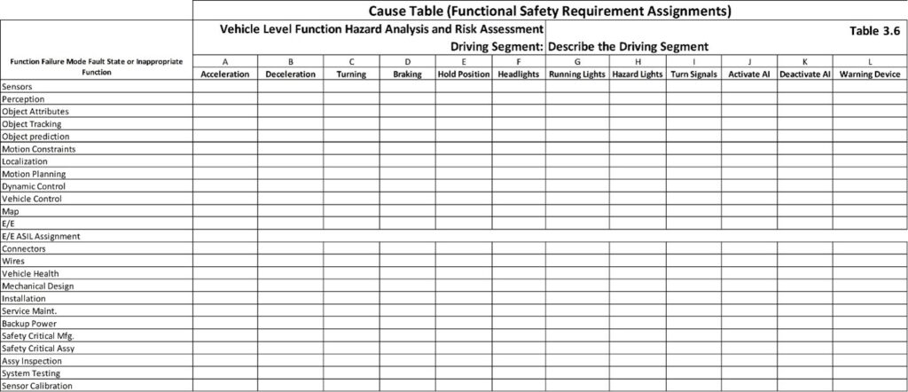
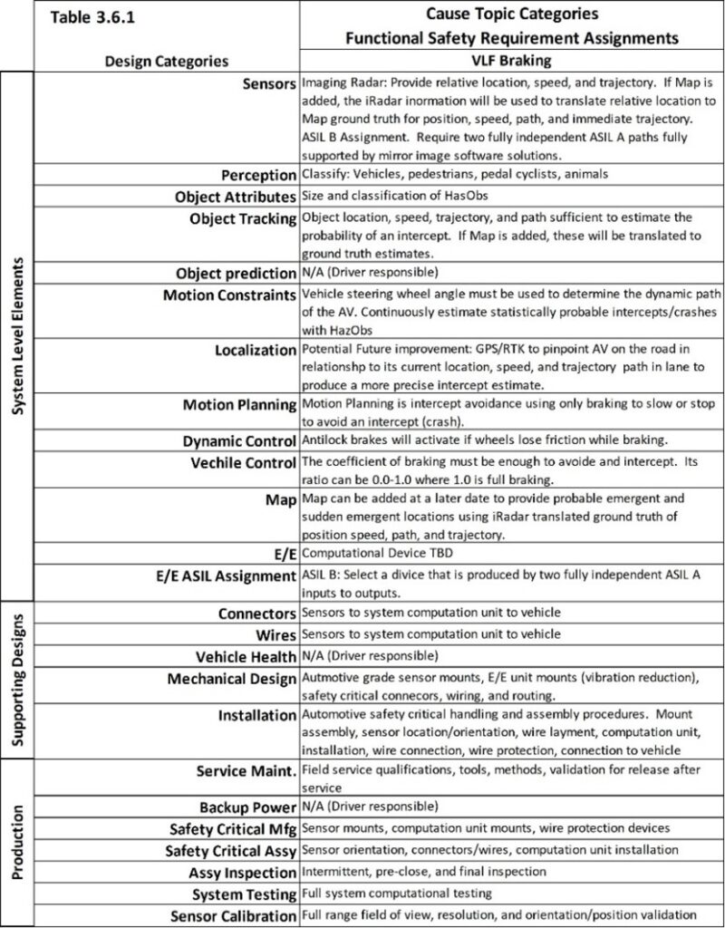
Table 3.6.1 is an L1 example for a crash avoidance system that autonomously activates brakes. The system monitors forward HazObs that are in lane or moving into the forward path on a simple intercept path. One of the obvious capability constraints is that the system assumes that the vehicle is going straight and all forward objects/HazObs are at risk. This is the same assumption as poorly designed dynamic cruise control systems that pick a target from the wrong lane on a curved road. The AV must be able to perform, as a minimum, basic AV current path analysis as it relates to the relative position and paths of objects and HazObs within or approaching the crash zone. At this point in the analysis, the system can add feedback from the vehicle’s steering control module (SCM). The steering wheel angle is either commanded by the driver or by an SAE-L1 lane-centering autonomous command. The SCM publishes the steering position on the vehicle’s CAN and from this the rate of change and acceleration of steering wheel position change can be calculated (the arc is becoming larger/smaller). The steering wheel angle will allow 1 Controls (Figure 3.12) to calculate the arc of the AV’s path. The dimensions of the AV will become an overlay on this planned path (the width and length of the vehicle that might hit a HazOb). The AV will be able to predict HazObs that are on, or are moving into, the AV’s actual path. The current actual AV trajectory can be overlaid onto the iRadar’s signal. The results will be a reduced number of false emergency braking and increased number of correct emergency braking.
The next section covers the assessment of risks and the creation of safety goals. The classification of risks is based on Severity, Exposure and Controllability and ends with the assignment of Automotive Safety Integrity Levels A, B, C, or D. An ASIL D is the most severe risk assignment. The assignment takes place in the bottom rows of Table 3.4. Safety goals are assigned to each function for each representative road segment analysis. ISO 26262 requirements are based on ASIL assignments.
ISO 26262 Part 3-6.4.3 Classification of hazardous events
If the scope of the analysis is too small, the assignment of risk will be QM safety critical and assigned to the IATF 16949 safety-critical function management process.
ISO 26262 Part 3-6.4.3.1 All hazardous events identified in 6.4.2 will be classified. The classification will be based on the driving segments studied in each Table 3.4. The hazardous events are the pre-crash scenarios described in Tables 3.21 through 3.41 and allocated to misbehaving and inappropriate VLFs in Table 3.4. The severity of the pre-crash scenario will be based on the injury and fatality rates and the HazOb exposures of each segment studied. The level of controllability by a driver for SAE L1, L2 and L3 designs can be assessed. Controllability is the likelihood that a driver can assume control and avoid the pre-crash scenario.
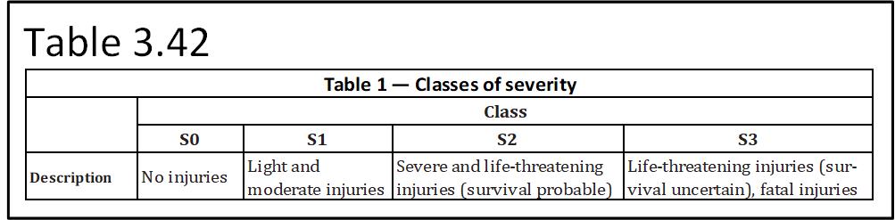
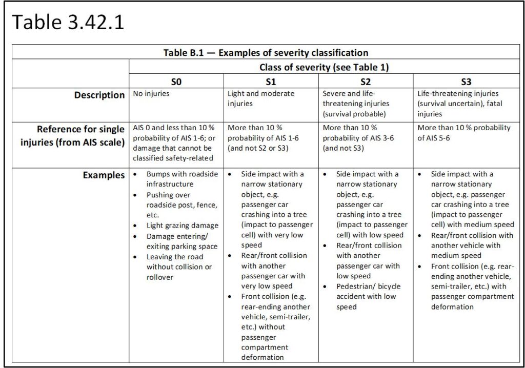
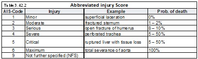
ISO 26262 Part 3-6.4.3.2 The severity of potential harm will be estimated based on a defined rationale for each hazardous event. The severity will be assigned to one of the severity classes S3, S2, S1 or S0 in accordance with Table 1 (Table 3.42 and 3.42.1). If the probability of a critical injury or death (AIS 5 or 6 – Table 3.42.2) is 10% or greater, severity is S3. If the probability of significant injury of AIS 4-6 is 10% or greater but not an S3, severity is an S2. If the probability of an AIS 1-6 injury is greater than 10% but not an S2, severity is an S1. Anything less, including only property damage, is an S0. This produces a more objective level of severity risk.
ISO 26262 Part 3-6.4.3.3 There are operational situations that result in harm (e.g. an accident). The pre-crash scenarios are created when the intended safe path, acceleration, deceleration, braking, stopping, holding positions are violated. This topic is thoroughly covered in previous conversations.
ISO 26262 Part 3-6.4.3.4 The severity class is S0 if the malfunctioning behavior is limited to material damage. No ASIL is assigned.
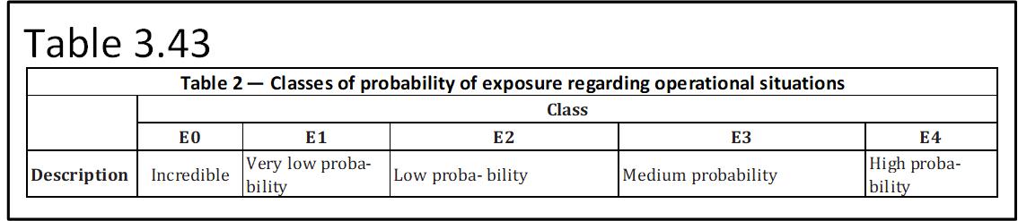
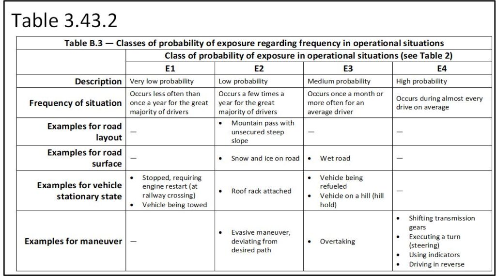
ISO 26262 Part 3- 6.4.3.5 The exposure to HazObs for each representative road segment in relationship to each pre-crash scenario (Table 3.4) as related to the HazObs in each segment (Table 3.5). Table 3.43 (ISO 26262-3 Table 2) is used to select an appropriate exposure for each representative road segment. The exposure for representative road segments is considered at the most complex time of day.
ISO 26262 Part 3-6.4.3.6 The number of vehicles is not part of the conversation. Exposure relates solely to the probability that HazObs are located in the areas that will be wrongly intruded by the AV’s specific VLF failure modes and their related hazards as are identified by Table 3.4.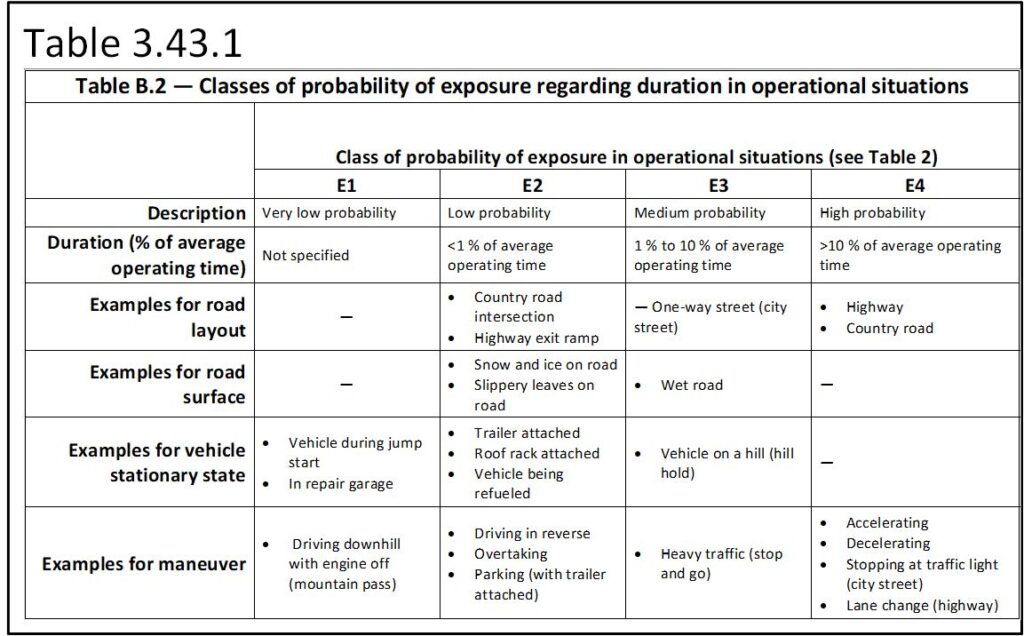
6 ISO 26262 Part 3-.4.3.7 Class E0 is used when no HazObs are present or the conditions required to create the scenario are an ‘act of God’, such as a plane landing on the road in front of the AV. Act of God exposure approaches a 0% probability. An E0 assignment would be most county roads in North Dakota or Wyoming.
Exposure is further clarified in Tables 3.43.1 (ISO 26262-3 Table B.2) and 3.43.2 (ISO 26262-3 Table B.3). The goal is to select an exposure that best reflects reality. For any company, an honest ASIL D solution with its supporting work product and safety case will be better in court than an argued ASIL C with less stringent requirements. The goal is to make the risk assessment objectively arguable.
ISO 26262 Part 3-6.4.3.8 The controllability of each hazardous event, by the driver or other persons involved in the operational situation, will be estimated based on a defined rationale for each hazardous event. Controllability risk numbers are defined in Table 3.44. Controllability is the ease with which the driver can assume control and avoid the hazardous events specific to each VLF failure mode’s pre-crash scenario (Table 3.4). The driver would have to take control of the faulty steering, acceleration, deceleration, braking, stop and hold position, and transmission controls. If there is no driver in the loop (L4 or L5), controllability is C3. A general domain L3 is a C3 because the human mind will be disengaged. As has been seen too often, current general domain SAE L3, full self-driving, AKA L2+ will not recognize the risks and will drive straight into a crash. The driver will have zero chance of reacting to a sudden emergent or other catastrophic failure. And it is possible that the driver has fallen asleep or is too involved in other activities (e.g. watching a movie or texting).
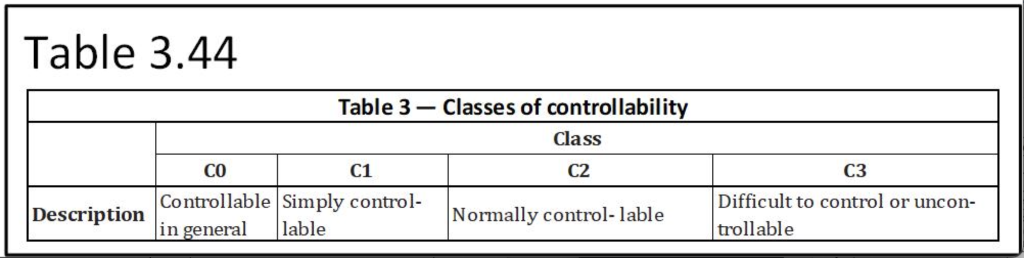
L1 and L2 solutions are usually simply controllable (C1) because the driver is required to monitor the driving environment and keep their hands on the steering wheel. L3 solutions can range from C1 to C3 based on the solution. For example, an L3 traffic-jam pilot would be simply controllable by the driver. There is little chance that the driver will become so engrossed in other things that they cannot take over quickly. The speeds will be low, so the hazard energy will be low (very low risk of injury). The system can be designed such that an early warning system will be able to warn the driver that the system is failing or that the system reached the maximum driving environment complexity it can resolve. Latency monitoring can be used to detect excessive complexity and activate a safety mechanism or minimum risk condition. In start-and-stop traffic, it is safe for the AV to slow to a stop and wait for the driver to assume control.
ISO 26262 Part 3-6.4.3.9 Class C0 does not involve a violation of a functional safety VLF.
ISO 26262 Part 3-6.4.3.10 ASIL is the relationship of risk based on severity, the probability of exposure and the driver’s controllability of the pre-crash scenario. Each representative road segment HARA (analyzed by Tables 3.4, 3.5, and 3.6) receives its own ASIL based on Table 3.32 (ISO 26262-3 Table 4).
ISO 26262 Part 3-6.4.3.11 When complex scenario relationships have to occur at the same time to create the pre-crash scenario, the probability of the event is ‘incredibly small’ and QM will be applicable. The representative driving segment will need to have this complexity documented.
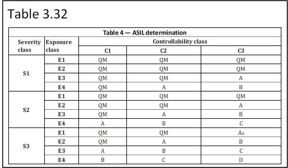
For the emergency crash avoidance system, injury and fatality are considered together, and the severity classification is S3. Exposure considers only the most complex representative road segments. In these segments, the AV is always exposed to a potential pre-crash scenario forward collision and is an E4. Consider that the HARA analysis suggests that 53% of all crashes relate to this study (the HARA – Table 3.4.1), which means exposure is extreme. When the system fails and warns the driver, it is easily controllable, which is a C1. According to the Table 4 above, this combination produces an ASIL B. This update has been added to Table 3.4.1.
ISO 26262 Part 3-6.4.4 Determination of safety goals
ISO 26262 Part 3-6.4.4.1 The safety goal is the goal of the ideal function. If it is achieved, the failure modes will be avoided. The majority of the AV right-of-way violations caused by other vehicles, pedestrians and pedal cyclists will be avoided. Each VLF from each representative road segment from the HARA that has an ASIL requires at least one safety goal. The safety goal is dependent on the VLF failure modes, their pre-crash scenario and relationships to the HazObs. If the safety goal is satisfied, the VLF will avoid causing harm and the design is free of that specific unreasonable risk. VLF safety goals can be combined into a more comprehensive safety goal. The conditions that precede a specific classification of pre-crash scenario will have structural differences between representative road segments. The physical patterns will have similarities but distances, speeds and road structure constraints will be different. This leads to different functional safety requirement assignments. The non-HazOb objects will have patterns that must be separated from the HazOb and driveable surface patterns. All fingerprints are different from each other but belong to the category of fingerprint. All fingerprints can be detected as different from toeprints.
ISO 26262 Part 3-6.4.4.2 Each VLF with an ASIL receives its safety goal. The VLF receives the highest ASIL across all representative road segments. Common safety goals are combined. The failure modes for emergency forward crash avoidance relate to the braking function: send emergency-brake-command. The risky failure modes are does not send-emergency-brake-command, incompletely send-emergency-brake-command, unevenly send-emergency-brake-command (biased high or low) and send-emergency-brake-command too slowly. The safety goal is to avoid hitting a forward vehicle, pedestrian or pedal cyclist that, based on their position or movement, will have a forward intercept with the front of the vehicle. Stating this more simply, the safety goal is to safely emergency stop before hitting a forward vehicle, pedestrian or pedal cyclist. There are four failure modes that result from design weaknesses in the functional sequences between the sensor to vehicle level function ‘send emergency brake command’. The functional safety requirements will address every potential reason for each of these four failure modes. This goal has been added to Table 3.4.1.
ISO 26262 Part 3-6.4.4.3 Safety goals with their ASIL will define specifications for all VLFs that if met will avoid creating pre-crash scenarios and their potential hazards (ISO 26262-8:2018, Clause 6). Lateral and longitudinal statistical capability was addressed in HARA part 2 of 3. Fully safe specifications begin when the passing and stopping distances are greater than 6sx,y,z,v. This is the AV’s 2Cpk velocity-based capability of following its planned path.
ISO 26262 Part 3-6.4.4.4 Each representative driving segment receives at least one set of tables 3.4, 3.5 and 3.6 along with notes and reasoning for the assigned ASIL to each VLF. The assignment of ASILs and their supporting reasoning/assumptions are included in the systems level integration validation (ISO 26262-4:2018, Clause 8). When the study is completed, each VLF receives the highest ASIL assigned across all the ODD’s representative road segments. In other words, if lighting receives 90 QMs and 1 ASIL A, it is an ASIL A.
ISO 26262 Part 3 4.6 Verification
ISO 26262 Part 3-6.4.6.1 The HARA and its safety goals needs to be verified (ISO 26262-8, Clause 9). The identification of the representative driving segments needs to show that the ODD has been properly represented; this includes driving times of day and potentially weather conditions. The complexity of the driving environment in each representative road segment must be defined: road type, road geometry, straight road, curved road, uphill, downhill, crest of road, locations of vehicles, pedestrians, pedal cyclists, time of day, weather conditions, and so on.
In closing, this section covers the approach that links VLFs failure modes/fault states to each NHTSA pre-crash scenario. It ends with the assignment of rational safety goals that define when each VLF is free from unreasonable risk. It covers a methodology to assign functional safety requirements to each concept design element so that the safety goals can be achieved.
Each representative road segment must be analyzed to document the HazObs present, the AV’s planned path through the segment, and how rationally predictable emergent and sudden emergent patterns form. Safety goals state the requirement of VLFs in producing measurable and verifiable reductions of NHTSA’s crash table risks. Functional safety requirements must be assigned to concept design elements and their functions that will avoid the risks of each VLF failure mode in each representative road segment. New elements, functions, and interrelationships between concept functions must be added. All knowable risks must have functional safety requirements such that the safety goals can be achieved. The next step is to develop a functional safety concept that combines all concept functional sequences and interrelationships from sensors to VLFs. Every concept function failure mode will be evaluated and turned into a 7FM fault state map. Fault detections will be designed to detect every concept function failure mode/fault state. Safety mechanisms will be designed for every detected failure mode/fault state. Fault tolerance time intervals will be established. The initial E/E hardware design will be decomposed such that there is a minimum of two (ASIL A/B) or four (ASIL C/D) decomposed and fully functional E/E paths between sensors and VLFs. Sensor strengths and weaknesses will be established. Individual sensor degradation monitoring will be designed. Sensor coverage will ensure sensor ASIL requirements are never violated by the failure of any given sensor. This will produce the functional safety concept. This is the starting level system design.